标准光模块

CFP 100GBASE-LR4 module
Specifications
- 产品型号: CFP-100GBASE-LR4
- 兼容品牌: 全系列
- 封装类型: CFP
- 传输速率: 100G
- 传输距离: Up to 10km transmission
- 发射波长: CWDM
- 接收波长: CWDM
- 工作温度: 商业级0℃~+70℃/工业级-40℃~+85℃ 可选
- 数字诊断: 带DDM
- 接收灵敏度: Up to 10km transmission
- 接收灵敏度: Up to 10km transmission
Description
F-tone CFP 100GBASE-LR4 module
supports a link length of 10 kilometers on standard single-mode fiber (SMF, G.652). 100 Gigabit Ethernet signal is carried over four wavelengths. Multiplexing and demultiplexing of the four wavelengths are managed within the device.
- CFP MSA package with duplex LC connector(straight/angled)
- Integrated heat sink optional
- Supports multi-rate from 103.1Gb/s to 111.8Gb/s aggregate
- Lane bit rate 25.78 Gb/s GbE, 27.95 Gb/s OTU4
- Up to 10km transmission on SMF
- EML laser and PIN receiver
- High speed I/O electrical interface (CAUI)
- MDIO interface with integrated digital diagnostic monitoring
- Single +3.3V power supply
- Maximum power consumption 16 W
- Operating case temperature: -5°C to +70°C
- Compliant to RoHS Directive 2011/65/EU
Ordering information:
| Part No. | Data Rate | Fiber | Distance | Interface | Temp. | DDMI |
| CFP-161HG-10-L | 103Gbps | SMF | 10km | LC | Standard | Yes |
| CFP-161HG-10-LA | 112Gbps | SMF | 10km | LC | Standard | Yes |
CFP Wiki
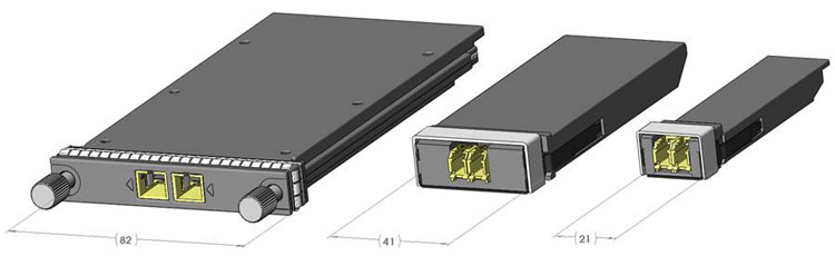
The CFP Multi-Source Agreement (MSA) defines hot-pluggable optical transceiver form factors to enable 40Gb/s and 100Gb/s applications, including next-generation High Speed Ethernet (40GbE and 100GbE). Pluggable CFP, CFP2 and CFP4 transceivers will support the ultra-high bandwidth requirements of data communications and telecommunication networks that form the backbone of the internet.
CFP MSA Operating Rules Issue 1.3
CFP MSA 100G Roadmap and Applications
CFP 100GE-SR10 Applications
Next Gen PMD CFP MSA Baseline Specifications
High Speed TX & RX Pin Separation
OIF Multi-Link Gearbox (MLG) Project Start Proposal
100Gb/s & Beyond Ethernet Optics
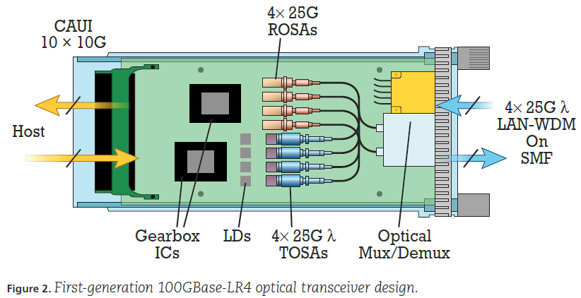
The first-generation 100GBase-LR4/ER4 optical transceiver architecture is similar to that of the 40GBase-LR4, but with the speed of the active optoelectronic components increased to 28Gbps for realizing a 4x28G optical interface. Additionally, the CAUI electrical interface defined in IEEE 802.3ba-2010 is widened from 4x10G lanes to 10x10G lanes. A 10:4/4:10 “gearbox” serializer/deserializer IC is used to implement the electrical interface between the 10-lane host data path and the four-lane optical data path.
The optical interface defined in IEEE 802.3ba-2010 uses a four-wavelength LAN-WDM 800-GHz wavelength grid in the 1310-nm band and optical multiplexing/de-multiplexing on single mode fiber. The transmitter optical specifications for LR4 and ER4 are based on cooled electro-absorption modulation with integrated DFB (EA-DFB) laser technology, but were written to allow eventual implementation with directly modulated DFB lasers for smaller size, lower power consumption, and lower cost TOSAs.
The receiver optical specifications for LR4 and ER4 are based upon PIN-PD detector technology with integrated TIA. The receiver specification also includes optical amplification, such as from a semiconductor optical amplifier, to compensate for optical fiber attenuation loss in the ER4 40-km application.
These components are packaged into the CFP pluggable module (previously shown in figure 1) with non-coaxial, 28-Gbps electrical connections between the discrete component TOSAs, ROSAs, and gearbox IC, as shown in figure 2 below.
The first-generation 100Gbase-LR4 module power dissipation is typically in the range of 24 W, which poses significant thermal management challenges for system designers, particularly as they seed to increase 100GbE optical port density. Thus, there is strong motivation to significantly reduce the 100GBase-LR4 optical transceiver module power dissipation in the next-generation design.
by fiberopticsforsale (Colin Yao)
TX&Sensetivity LCFP LR4
OTU4 4I1-9D1F Operation
| Parameter | Symbol | Min. | Typical | Max. | Unit |
| Transmitter | |||||
| Signaling Speed per Lane | BRAVE | 27.95 | Gbps | ||
| Lane_0 Center Wavelength | λC0 | 1294.53 | 1295.56 | 1296.59 | nm |
| Lane_1 Center Wavelength | λC1 | 1299.02 | 1300.05 | 1301.09 | nm |
| Lane_2 Center Wavelength | λC2 | 1303.54 | 1304.58 | 1305.63 | nm |
| Lane_3 Center Wavelength | λC3 | 1308.09 | 1309.14 | 1310.19 | nm |
| Total Average Output Power*(Note4) | Po | - | 8.9 | dBm | |
| Average Launch Power per Lane | Peach | -2.5 | 2.9 | dBm | |
| Side Mode Suppression Ratio | SMSR | 30 | dB | ||
| Optical Return Loss Tolerance | 20 | dB | |||
| Extinction Ratio*(Note5) | ER | 7 | dB | ||
| Transmitter eye mask definition {X1,X2, X3, Y1, Y2, Y3}*(Note5) | G.959.1 Compliant | ||||
| TX Disable Assert Time | t_off | 100 | us | ||
| Receiver | |||||
| Signaling Speed per Lane | BRAVE | 27.95 | Gbps | ||
| Lane_0 Center Wavelength | λC0 | 1294.53 | 1295.56 | 1296.59 | nm |
| Lane_1 Center Wavelength | λC1 | 1299.02 | 1300.05 | 1301.09 | nm |
| Lane_2 Center Wavelength | λC2 | 1303.54 | 1304.58 | 1305.63 | nm |
| Lane_3 Center Wavelength | λC3 | 1308.09 | 1309.14 | 1310.19 | nm |
| Average Receive Power per Lane | Rpow | -8.8 | 2.9 | dBm | |
| Receive Sensitivity per Lane*(Note7) | Pmin | -10.3 | dBm | ||
| Receiver Overload | Pmax | 5.5 | dBm | ||
| Optical Return Loss | ORL | -26 | dB | ||
| LOS Assert | LOSA | -12.7 | dBm | ||
| LOS De-Assert | LOSD | -10.7 | dBm | ||
| LOS Hysteresis | 0.5 | dB | |||
100GBASE-LR4 Operation
| Parameter | Symbol | Min. | Typical | Max. | Unit |
| Transmitter | |||||
| Signaling Speed per Lane | BRAVE | 25.78 | Gbps | ||
| Lane_0 Center Wavelength | λC0 | 1294.53 | 1295.56 | 1296.59 | nm |
| Lane_1 Center Wavelength | λC1 | 1299.02 | 1300.05 | 1301.09 | nm |
| Lane_2 Center Wavelength | λC2 | 1303.54 | 1304.58 | 1305.63 | nm |
| Lane_3 Center Wavelength | λC3 | 1308.09 | 1309.14 | 1310.19 | nm |
| Total Average Output Power*(Note4) | Po | 10.5 | dBm | ||
| Average Launch Power per Lane | Peach | -4.3 | 4.5 | dBm | |
| Side Mode Suppression Ratio | SMSR | 30 | dB | ||
| Optical Return Loss Tolerance | 20 | dB | |||
| Extinction Ratio*(Note10) | ER | 4 | dB | ||
| Transmitter eye mask definition {X1,X2, X3, Y1, Y2, Y3}*(Note10) | IEEE 802.3ba-2010 Compliant | ||||
| TX Disable Assert Time | t_off | 100 | us | ||
| Receiver | |||||
| Signaling Speed per Lane | BRAVE | 25.78 | Gbps | ||
| Lane_0 Center Wavelength | λC0 | 1294.53 | 1295.56 | 1296.59 | nm |
| Lane_1 Center Wavelength | λC1 | 1299.02 | 1300.05 | 1301.09 | nm |
| Lane_2 Center Wavelength | λC2 | 1303.54 | 1304.58 | 1305.63 | nm |
| Lane_3 Center Wavelength | λC3 | 1308.09 | 1309.14 | 1310.19 | nm |
| Average Receive Power per Lane | Rpow | -10.6 | 4.5 | dBm | |
| Receive Sensitivity in OMA per Lane*(Note7) | Pmin | -8.6 | dBm | ||
| Receiver Overload | Pmax | 5.5 | dBm | ||
| Optical Return Loss | ORL | -26 | dB | ||
| LOS Assert | LOSA | -13.6 | dBm | ||
| LOS De-Assert | LOSD | -11.6 | dBm | ||
| LOS Hysteresis*(Note9) | 0.5 | dB | |||
For more details and most updated date please refer to pdf
Related Products

CFP-100G-SR10
- Transmission data rate up to 11.2Gbit/s per channel
- CFP MSA compliant
- Compliant to IEEE 802.3ba specification for 100GBASE-SR10 links
- Up to 11.2 Gbps per channel bandwidth,
- OTU4 compatible
- 10 channels 850nm VCSEL array
- 10 channels PIN photo detector array
- OM3 Multimode Fiber cable of up to 300m and OM4 Multimode Fiber cable of up to 400m
- MDIO digital diagnostic and control capabilities.
- compliant to CFP MSA Management Interface Specification, Draft 1.4
- TX input and RX output CDR retiming
- Hot pluggable electrical interface
- Power class 1 (<8W max)
- Operating case temperature 0°C to +70°C
- 3.3V power supply
- RoHS 6 compliant(lead free)

CFP-40G-SR4
- Transmission data rate up to 11.2Gbit/s per channel
- CFP MSA compliant
- Compliant to IEEE 802.3ba specification for 40GBASE-SR4 links
- Up to 11.2 Gbps per channel bandwidth,
- OTU3 compatible
- 4 channels 850nm VCSEL array
- 4 channels PIN photo detector array
- OM3 Multimode Fiber cable of up to 300m and OM4 Multimode Fiber cable of up to 400m
- MDIO digital diagnostic and control capabilities.
- compliant to CFP MSA Management Interface Specification, Draft 1.4
- TX input and RX output CDR retiming
- Hot pluggable electrical interface
- Power class 1 (<8W max)
- Operating case temperature 0°C to +70°C
- 3.3V power supply
- RoHS 6 compliant(lead free)

CFP-40G-LR4
- Transmission data rate up to 11.2Gbps per channel
- CFP MSA compliant
- Compliant to IEEE 802.3ba specification for 40GBASE-LR4 links
- OTU3 compatible
- 1310nm Un-cooled CWDM DFB-DML ,Transmitter and optical MUX
- High Sensitivity PIN-TIA and optical DEMUX
- 1271, 1291, 1311, 1331nm CWDM grid in ITU-T G.694.2 up to 10km over a SMF
- MDIO digital diagnostic and control capabilities.
- compliant to CFP MSA Management Interface Specification, Draft 1.4
- TX input and RX output CDR retiming
- Hot pluggable electrical interface
- Power class 1 (<8W max)
- Operating case temperature 0°C to +70°C
- 3.3V power supply
- RoHS 6 compliant(lead free
100G Ethernet 10km CFP Optical Transceiver Module
F-tone’s CFP-100G-LR4 100GE CFP transceiver modules are designed for use in 100 Gigabit Ethernet links over single mode fiber. They are compliant with the CFP MSA and IEEE 802.3ba 100GBASE-LR4. Digital diagnostics functions are available via an MDIO interface, as specified by the CFP MSA and F-tone Application Note AN-2080. The transceiver is RoHS-6 compliant and lead-free per Directive 2002/95/EC, and F-tone Application Note AN-2033.
40G NRZ VSR Multi-Rate CFP Optical Transceiver Module
F-tone’s CFP-40GNRZ-VSR 40G CFP transceiver modules are designed for use in 40 Gigabit links required for router to router client side applications or uplink interconnections to transport networks. Designed to enable optical compatibility with existing carrier client interfaces VSR2000-3R2 per ITU-T G.693, they are compliant with the CFP MSA, IEEE 802.3bg 40GBASE-FR and OTU3 requirements specified in ITU-T G.709. Digital diagnostics functions are available via an MDIO interface, as specified by the CFP MSA. The transceiver is RoHS-6 compliant and lead-free per Directive 2002/95/EC.

40G Ethernet 100m CFP Optical Transceiver Module
F-tone’s CFP-40G-100M 40G CFP transceiver modules are designed for use in 40 Gigabit Ethernet links over multimode fiber. They are compliant with the CFP MSA and IEEE 802.3ba 40GBASE-SR4. Digital diagnostics functions are available via an MDIO interface, as specified by the CFP MSA and F-tone Application Note AN-2078. The transceiver is RoHS-6 compliant and lead-free per Directive 2002/95/EC, and F-tone Application Note AN-2012.