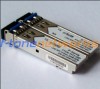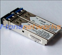
Product Features
● VCSEL LASER
● GaAs PIN-TIA Photodiode Receiver
● 50/125μm MMF , 62.5/125MMF
● Transceiver SFP Footprint
● LC Optical Interface
● Compliant With SFP MSA and SFF-8472
● Digital Diagnostic Monitoring Interface
● Single +3.3V Power Supply
● CML Differential Inputs and Outputs
● LVTTL Signal Detection Output
● Compliant With ITU-T G.957
● Compliant With RoHS and Lead Free
● Metal Enclosure for Lower EMI
● Operating Case Temperature:
Standard: 0 to +70℃
Extend: -20 to +85℃
Industrial: -40 to +85℃
Product Applications
● Fast Ethernet
● ATM/SONET/SDH
● Switch/Router
● Other Optical Transmission Systems
Absolute MaximumRatings
| Parameter | Symbol | Min | Max | Unit | |
| Storage Temperature | Tst | -40 | +85 | °C | |
| Operating Temperature | TO | BYCS-8512-02D | 0 | +70 | °C |
| BYCS-8512-02DE | -20 | +85 | °C | ||
| BYCS-8512-02DI | -40 | +85 | °C | ||
| Input Voltage | – | GND | VCC | V | |
| Power Supply Voltage | VCC-VEE | 0 | +3.6 | V | |
Recommended OperatingConditions
| Parameter | Symbol | Min | Typ | Max | Unit | |
| Storage Temperature | Tst | -40 | – | +85 | °C | |
| Operating Case Temperature | TC | BYCS-8512-02D | 0 | – | +70 | °C |
| BYCS-8512-02DE | -20 | – | +85 | °C | ||
| BYCS-8512-02DI | -40 | – | +85 | °C | ||
| Power Supply Voltage | VCC | 3.1 | 3.3 | 3.5 | V | |
| Power Supply Current | ICC | – | – | 200 | mA | |
| Data Rate | DR | – | 1250 | – | Gbps | |
OpticalSpecification
| Transmitter | |||||||
| Parameter | Symbol | Min | Typ | Max | Unit | Note | |
| Center Wavelength | vcsel | lC | 830 | 850 | 860 | nm | |
| Spectral Width | Dl | – | – | 0.85 | nm | – | |
| Average Optical Output Power | Po | -9.5 | – | -3 | dBm | 62.5um MMF | |
| Extinction Ratio | ER | 9 | – | – | dB | – | |
| Optical Rise/Fall Time(20%-80%) | Tr/Tf | – | – | 0.26 | ns | – | |
| Output Eye Diagram | Compliant with ITU-T G.957 | ||||||
| Receiver | |||||||
| Parameter | Symbol | Min | Typ | Max | Unit | Note | |
| Operate Wavelength | – | 770 | 850 | 870 | nm | ||
| Receiver Sensitivity | RSENS | – | – | -18 | dBm | 1 | |
| Receiver Saturation | PRS | -3 | – | – | dBm | 1 | |
| LOS Assert | – | -48 | – | – | dBm | Alarm: High-level | |
| LOS De-Assert | – | – | – | -19 | dBm | ||
| LOS Hysteresis | – | 0.5 | – | 5 | dBm | – | |
ElectricalSpecification
| Transmitter | |||||||
| Parameter | Symbol | Min | Typ | Max | Unit | Note | |
| Power Supply Current | ICCT | – | 70 | 120 | mA | 2 | |
| Input Differential Impedance | ZIN | 90 | 100 | 110 | Ω | – | |
| Input Swing Differential Voltage | VIN | 500 | – | 2400 | mV | 3 | |
| TX-Disable Voltage | Disable | – | 2.0 | – | VCC | V | – |
| Enable | – | 0 | – | 0.8 | V | – | |
| TX-Fault Voltage | Fault | – | 2.0 | – | VCC | V | – |
| Normal | – | 0 | – | 0.8 | V | – | |
| Receiver | |||||||
| Parameter | Symbol | Min | Typ | Max | Unit | Note | |
| Power Supply Current | ICCR | – | 600 | 80 | mA | 2 | |
| Output Swing Differential Voltage | VOUT | 600 | – | 2000 | mV | 4 | |
| LOS Voltage | High | – | 2.0 | – | VCC | V | – |
| Low | – | 0 | – | 0.8 | V | – | |
2. The current excludes the output load current.
3. CML input, internally AC-coupled and terminated.
4. Internally AC-coupled.
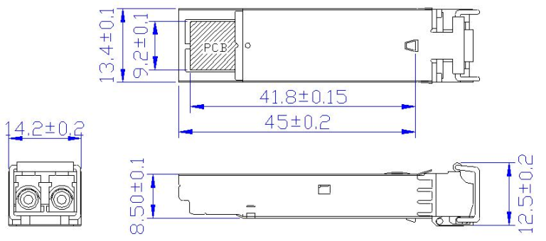
Package Diagram
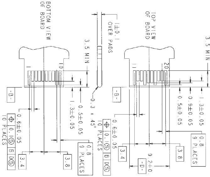
Board Layout Hole Pattern
LC Side Interface
OrderInformation
| 产品型号 | 封装 | 波长(-xx) | 速率(xx) | 传输距离 (-xx) | x | 温度(x) |
| BYCS-8512-02Dxx | SFP | 85=850nm 13=1310nm 15=1550nm |
12=1.25GBP/s | 02=500m | 空 不带DDM D 带DDM |
空 商业级 E 拓展级 I 工业级 |