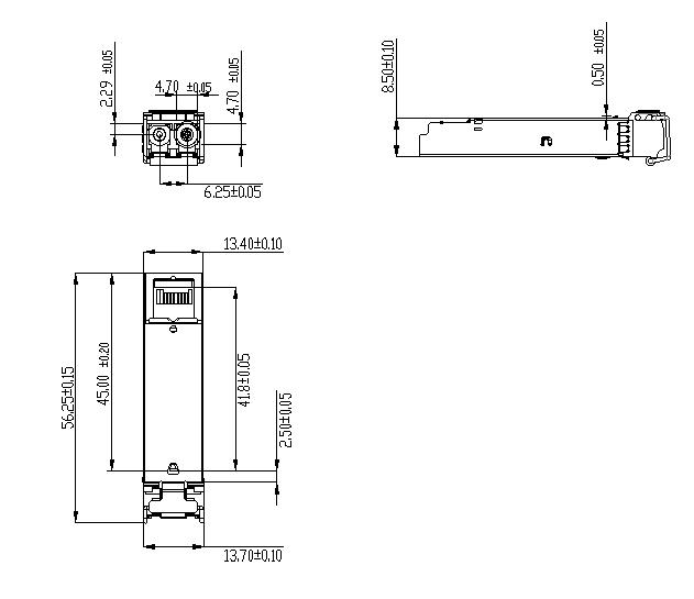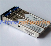
Product Features
- Supports up to 1.25Gbpsbit rates
- Hot-pluggable SFP footprint
- 1310nm FPlaser and PIN photo detector, Up to 20kmfor SMF transmission
- Compliant with SFP MSA and SFF-8472 with duplexLC receptacle
- Compatible with RoHS
- Single +3.3V power supply
- Real Time Digital Diagnostic Monitoring
- ≤500VAC
- Operating case temperature:Standard: 0 to +70°C/Industrial: -40 to +85°C
Applications
- 25Gbps Optical systems
- Gigabit Ethernet
- 063GbpsFiber Channel
- Other Optical links
Description
The SFP transceivers are high performance, cost effective modules supporting data rate of 1.25Gbps and 20km transmission distance with SMF.The transceiver consists of three sections: a FP laser transmitter, a PIN photodiode integrated with a trans-impedance preamplifier (TIA) and MCU control unit. All modules satisfy class I laser safety requirements.The transceivers are compatible with SFP Multi-Source Agreement and SFF-8472 digital diagnostics functions.
Absolute Maximum Ratings
|
Parameter |
Symbol |
Min |
Max |
Unit |
|
Supply Voltage |
Vcc |
-0.5 |
4.5 |
V |
|
Storage Temperature |
Ts |
-40 |
+85 |
°C |
|
Operating Humidity |
- |
5 |
85 |
% |
Recommended Operating Conditions
|
Parameter |
Symbol |
Min |
Typical |
Max |
Unit |
|
|
Operating Case Temperature |
Standard |
Tc |
0 |
+70 |
°C |
|
|
Extended |
-20 |
+80 |
°C |
|||
|
Industrial |
-40 |
+85 |
°C |
|||
|
Power Supply Voltage |
Vcc |
3.135 |
3.30 |
3.465 |
V |
|
|
Power Supply Current |
Icc |
300 |
mA |
|||
|
Data Rate |
0.1 |
1.25 |
Gbps |
|||
Optical and Electrical Characteristics
|
Parameter |
Symbol |
Min |
Typical |
Max |
Unit |
Notes |
||
|
Transmitter |
||||||||
|
Centre Wavelength |
λc |
1260 |
1310 |
1360 |
nm |
|||
|
Spectral Width(RMS) |
Δλ |
3 |
nm |
|||||
|
Side-Mode Suppression Ratio |
SMSR |
- |
- |
- |
dB |
|||
|
Average Output Power |
Pout |
-9 |
0 |
dBm |
1 |
|||
|
Extinction Ratio |
ER |
9.0 |
dB |
|||||
|
Data Input Swing Differential |
VIN |
180 |
1200 |
mV |
2 |
|||
|
Input Differential Impedance |
ZIN |
90 |
100 |
110 |
Ω |
|||
|
TX Disable |
Disable |
2.0 |
Vcc |
V |
||||
|
Enable |
0 |
0.8 |
V |
|||||
|
TX Fault |
Fault |
2.0 |
Vcc |
V |
||||
|
Normal |
0 |
0.8 |
V |
|||||
|
Receiver |
||||||||
|
Centre Wavelength |
λc |
1260 |
1610 |
nm |
||||
|
Receiver Sensitivity |
-23 |
dBm |
3 |
|||||
|
Receiver Overload |
-1 |
dBm |
3 |
|||||
|
LOS De-Assert |
LOSD |
-24 |
dBm |
|||||
|
LOS Assert |
LOSA |
-38 |
dBm |
|||||
|
LOS Hysteresis |
0.5 |
4 |
dB |
|||||
|
Data Output Swing Differential |
Vout |
600 |
800 |
1000 |
mV |
4 |
||
|
LOS |
High |
2.0 |
Vcc |
V |
||||
|
Low |
0.8 |
V |
||||||
Notes:
1. The optical power is launched into SMF.
2. PECL input, internally AC-coupled and terminated.
3. Measured with a PRBS 27-1 test pattern @1250Mbps, BER ≤1×10-12.
4. Internally AC-coupled.